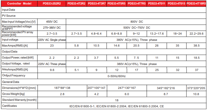
PDS33 Solar Pump Controller 2.2kW~18.5kW

- Schematic diagram of the solar pump system:

- Working Principle: The PDS33 solar pump system serves to provide water in remote applications where mains power is unreliable or unavailable. The controller can convert DC power from PV arrays to AC power, and control different types of pumps. On sunny days, the PDS33 solar pump system can pump water continuously. The system has no batteries or other energy storage devices.
Water should be taken to the storage tank for later use and the water sources are natural or special such as rivers, lakes, wells, water lines, etc. A float switch can be installed in the water tower to control the operation of the pump. And install a low-level probe in the well to detect well water so that when there is a shortage of water, the pump will stop. Figure 1 shows a typical diagram of a PDS33 solar pump system. The main parts and components of the system are listed after the diagram.
-PDS33 solar pump system is designed including:
A. Solar panels
B. DC Device Disconnector Switch or Disconnect Switch
C. PDS33 series solar pump controller 2.2kW~18.5kW
D. Pumps and motors
E. Water supply switch (optional)
F. Tank level switch (optional)
SPECIFICATIONS: